miniNAV
Indication
The miniNAV is used for draining cerebrospinal fluid from the ventricles into the peritoneum in hydrocephalus patients.
Technical description
The miniNAV was developed to offer a small-sized valve without the obstruction related problems that are known to arise in the treatment of hydrocephalus.
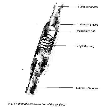
the miniNAV is composed of a robust titanium casing (1) whose proximal end contains a ball-cone valve. A spiral spring (2) maintains the opening pressure of the ball-cone valve and the sapphire ball (3) ensures the precise closure of the valve.The inlet connector (4) and the outlet connector (5) are also made of titanium.
Physics background
The intraventricular pressure is positive in a healthy human in a the horizontal position. To maintain this pressure through shunt drainage, one has to choose the appropriate pressure range, taking into account the abdominal cavity pressure. The resulting IVP is the sum of the shunt opening pressure and the abdominal cavity pressure.
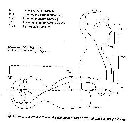
In a healthy human, the ventricular pressure in the vertical position becomes slightly negative. To maintain this pressure by means of shunt drainage, the shunt opening pressure has to be significantly higher so that the shunt can compensate fort he hydrostatic pressure minus the sum of the abdominal cavity pressure and the slightly negative intraventricular pressure.
Conventional shunts open immediately as soon as the patient stands up, which can lead to critical overdrainage.
Function of the miniNAV
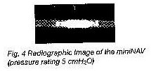
The operating principle of the miniNAV is illustrated in fig.3 and fig.4.
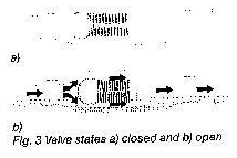
Fig.3a shows the miniNAV in the horizontal position. The ball-cone valve is closed and drainage is prevented.
If the patient’s IVP increases and continues tor ise, the spring pressure of the ball-cone unit will be overcome. The sealing ball will move away from to cone and a gap opens for fluid drainage.
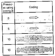
The miniNAV is available in 4 different pressure levels ( 0 ,5 ,10 ,15 cmH2O) the pressure setting should be chosen according to the clinical picture ( normal-pressure hydrocephalus, hypertonic hydrocephalus ).
In case the patient suffers from symptoms associated with overdrainage or complications with overdrainage are expected, we recommend implantation of the SHUNTASSISTANT in addition to the miniNAV. The SHUNTASSISTANT is a hydrostatic, supplementary valve specially designed for preventing problems with overdrainage. It is made by Christoph Miethke GmbH Co.KG.
The coding of the miniNAV can be identified according to the shapeof the valve’s housing. For example the miniNAV with an opening pressure of 5cmH2O has a concave proximal part ( curved inwards ) and a convex distal part ( curved outwords ).
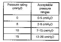
Each miniNAV is calibrated in accordance with strict quality control standards. The following pressure levels are available:
Possible shunt components
The miniNAV is available with different shunt accessories. These variants are comprised of a variety of components, which are described briefly introduced below:
The borehole reservoir is positioned in the cranial borehole. It allows measurement of intraventricular pressure injection of drugs and extraction of CSF. Its solid titanium base is highly puncture resistant. All reservoirs are available with integrated catheters or connectors. A special borehole reservoir is the SPRUNG RESERVOIR. An additional new feature of this reservoir is that CSF can be flushed towards the miniNAV because of a one way valve in the bottom of reservoir. By this mechanism flow in the direction of the ventricular catheter is avoided during the pumping procedure. The opening pressure of the shunt system is not increased by the implantation of the SPRUNG RESERVOIR.
The prechamber is positioned on the cranium. It allows measurement of intraventricular pressure, injection of drugs, extraction of CSF and palpatory ventricle inspection. Its solid titanium base is highly puncture-resistant. A puncture of the prechamber or the CONTROL RESERVOIR should be performed as perpendicularto the reservoir surface as possible with a cannula of maximum diameter 0.9mm.30 punctures are possible without any restrictions. A special prechamber is the CONTROL RESERVOIR. As an additional new feature of this reservoir, CSF can be flushed towards the miniNAV because of a one-way valve in the proximal inlet of the reservoir. By this mechanism flow in the direction of the ventricular catheter is avoided during the pumping procedure. The opening pressure of the shunt system is not increased by the implantation of the CONTROL RESERVOIR.
Tight tolerancing of the deflector ensures a good fit with the ventricular catheter. By adjusting the deflector (prior to implantation) the length of catheter penetrating into the skull can be optimised. The ventricular catheter is ‘’deflector’’ at a right angle in the borehole.
Tube systems
The miniNAV has been designed to ensure the optimal ventricular pressure. It is available as a shunt system or as individual valve units with or without an integrated distal catheter ( internal diameter 1.2mm, external diameter 2.5mm ) individual valve units should be used with catheters of approx. 1.2mm internal diameter and approx. 2.5 mm external diameter. The connector on the valve allows using catheters of 1.0mm to 1.5mm internal diameter. The external diameter of the catheter should be about double the internal diameter. Regardless the catheters must be carefully fixed with a ligature, to the valve connectors. It is essential that kinks in the catheter are avoided.
The included catheters have virtually no effect on the pressure-flow characteristics.
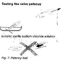
The miniNAV can be filled by aspiration through a sterile, single use syringe attached to the distal end of catheter.
The proximal end of the valve is immersed in a sterile, physiological saline solution. The valve is patent if fluid can be extracted in this way ( see fig.7 )
Valve test prior to implantation
Each miniNAV valve has been tested to ensure that the performance specifications given on the label are always met. The dynamic performance characteristics of the shunt can not be tested in a static test performed in the operating room.
If the surgeon wishes to verify, prior to implantation, that the shunt meets the specifications given by the manufacturer,the test described in the following can be carried out in the operating room:
Setting up the equipment
a) position the manometer and the water bath in such a way that the zero point of the manometer and the fluid level of the water bath are at the same height (see fig.8)
b) Fill the syringe, with the 5mm tip fitler attached with sterile water (always use the 5mm tip filter when topping up the syringe). Remove the tip filter when the syringe is full.
c) Connect the syringe, the manometer and the silicone tube with each other. Use the tube adapter if necessary (see fig8)
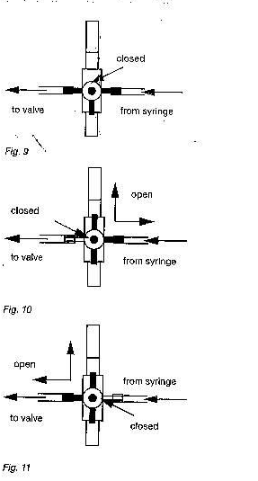
d) To release all air from the test assembly, turn the three-way faucet as shown in fig.9
e) Immerse the silicone tube in the sterile water bath and rinse it with the sterile water from the syringe.
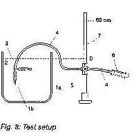
1 miniNAV a horizontal, b vertical; 2 water bath; 3 constant water level; 4 silicone tube; 5 three-way tap; 6 single-use syringe with syringe filter; 7 manometer
Calibrating the equipment
a) Turn the three-way faucet as shown in fig.10 and fill the manometer to at least 5cmH2O
b) With the silicone tube immersed in the water bath, turn the three-way faucet so that the syringe is isolated from the manometer (see fig.11)
c) Allow the water comlomn in the manometer to drop.
d) The manometer has know been calibrated to the zero-level of the water bath. Fixate the manometer to maintain its position in relation to the water bath.
Test procedure
a) Connect the sterile shunt to be tested to the ready assembled, sterile test equipment.
b) Turn the three-way faucet as shown in fig.10 and fill the manometer to 10 cmH2O above the expected opening pressure. ( example: for testing a miniNAV with an opening pressure setting of 5cmH2O, the manometer is filled to 15cmH2O.)
c) Turn the three-way faucet as shown in fig.9 so that the manometer is isolated.
d) Remove all air from the shunt and the test setup by carefully rinsing it through with sterile water from the syringe.
e) Immerse the sterile shunt in the sterile water bath. The distal part of the shunt must be under water to obtain valid test results.
f) Carefully maintain a flow through the shunt and turn the three-way faucet as shown in fig.11 to isolate the syringe. As soon as the three-way faucet is in the correct position, the water colomn should begin to drop. The syringe is now isolated from the valve and it is not necessary anymore to maintain its flow. Repeat steps b to f if the water column fails to drop.
g) Allow the water level in the manometer to drop for 2 to 2.5 minutes. Read the resulting pressure at the manometer.
Test results- pre-implantation test
The pressure readings obtained by this method should yield the following results:
Pressure-flow characteristics
The diagrams below show the pressure-flow characteristics fort he pressure ratings in which the miniNAV is available.
Test on reflow safety
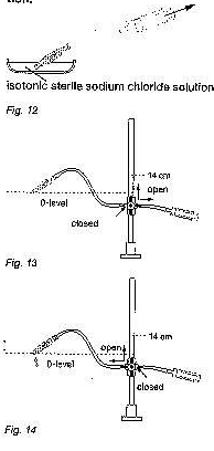
This test is carried out with the same equipment as the pre-implantation test. The shunt is carefully filled with sterile saline solution from the syringe before the air is removed from it (fig.11). the shunt is connected against the direction of flow (see arrow the shunt). The outlet of the shunt has to be at the zero level of the manometer. The manometer is filled up to 14 cmH2O (fig.12)
The three-way faucet is used for unblocking the flow to the shunt and blocking the flow to syringe. In this setup, no more than 2 drops (0.1 cc) per minute should emerge from the proximal part of the shunt (fig.13)
Caution: be careful to maintain sterility and to avoid particle contamination.
Surgical procedure
Positioning the ventricular catheter
Several surgical techniques are available for positioning the ventricular catheter. The necessary skin incision should be carried out, preferably, in the shape of a lobule pedicled towards the draining catheter or as a straight skin incision. To avoid CSF leakage, care should be taken that the dura opening is kept as small as possible after applying the borehole. The ventricular catheter is stiffened by the introducing stylet supplied with the product.
The miniNAV is available in different shunt variants:
When using a miniNAV-SHUNTSYSTEM with borehole reservoir or SPRUNG RESERVOIR, the ventricular catheter is implanted first. Once the introducing stylet has been removed, the patency of the ventricular catheter can be tested by checking if CSF is dripping out. The catheter is shortened and the borehole reservoir is connected, with the connection secured with a ligature. The skin incision should not be located directly above the reservoir.
The miniNAV-SHUNTSYSTEM with prechamber or CONTROL RESERVOIR comed with a deflector. This deflector is used for adjusting the position of deflection before implantation of the ventricular catheter. The catheter is deflected; the prechamber is put into place. The position of the ventricular catheter should be inspected again by postoperative CT or MR imaging.
Positioning the miniNAV
The miniNAV should be implanted in the head of the patient.
The valve is marked with an arrow pointing to distal(downwards) to indicate the flow direction. Whether the label faces towards the skin or the brain is of no importance in terms of the valve’s performance.
Following subcutaneous tunneling, the catheter is either pushed from the borehole, possibily through a reservoir, to the selected valve implantation site: or it is pushed through from the valve and connected to the reservoir, if there is any.
Positioning the peritoneal catheter
The access site for the peritoneal catheter is left to the surgeon’s discretion. It can be applied e.g. para-umbilically in a horizontal direction or transrectally at the height of epigastrium.
Likewise, various surgical techniques are available for positioning the peritoneal catheter.
We recommend pulling through the peritoneal catheter, using a subcutaneous tunneling tool and perhaps with an auxiliary incision, from the shunt to the intended position of the catheter. The peritoneal catheter, which is usually securely attached to the miniNAV has an open distal end, but no wall slits. Following the exposure of and the entry into, the peritoneum by means of a trocar, the peritoneal catheter (shortened, if necessary) is pushed forward into the open space in the abdominal cavity.
Re-implantation
Under no circumstances should products that have has previously been implanted in a patient be subsequently reimplanted in another, as a validated decontamination process will compromise the functionality of the valve.
Safety measures
The patients must be carefully monitored after the implantation. Reddened skin and tension in the area of the drainage tissue could indicate infections at the shunt system. Symptoms such as headache, dizzy, spells, mental confusion or vomiting are common occurances in cases of shunt dysfunction. Such symptoms, as well as shunt system leakage, necessitate the immediate replacement of the shunt component responsible, or of the entire shunt system.
Compatibility with diagnostic procedures
MRI examinations with field strengths of up 3.0 tesla and CT examinations can be carried without endangering or impairing the functionality of the shunt.
The miniNAV is MR conditional (ASTM-f2503-05). All components are visible via X-ray. The provided catheters are MRI safe. Reservoirs, deflectors and connectors are MR conditional.
Postoperative valve test
The miniNAV has been designed as a safe and reliable unit even without the implantation of a pumping device. However, the inclusion of a prechamber or a borehole reservoir allows the shunt system to be tested by flushing or pressure measurements.
Functional safety
The valves have been designed for long-term reliable and precise operation. Still, the possibility that the shunt system will need to be replaced for technical or medical reasons can not be excluded.
The valve and the valve system are able to resist positive and negative pressure up to 200cmH2O during and after implantation.
Sterilization
The products are sterilized with steam under closely monitored conditions. Double wrapping in sterile bags ensures sterility for a period of five years. The expiry date is printed on the wrapping of each individual product. Products taken from a damaged wrapping must not be used under any circumstances.
Resterilization
The descriptions and explanations given in this document are based on the clinical experience available to date. It is for the surgeon to decide if surgical procedures should be changed according to his or her experience and surgical practice.
The miniNAV is used for draining cerebrospinal fluid from the ventricles into the peritoneum in hydrocephalus patients.
Technical description
The miniNAV was developed to offer a small-sized valve without the obstruction related problems that are known to arise in the treatment of hydrocephalus.
the miniNAV is composed of a robust titanium casing (1) whose proximal end contains a ball-cone valve. A spiral spring (2) maintains the opening pressure of the ball-cone valve and the sapphire ball (3) ensures the precise closure of the valve.The inlet connector (4) and the outlet connector (5) are also made of titanium.
Physics background
The intraventricular pressure is positive in a healthy human in a the horizontal position. To maintain this pressure through shunt drainage, one has to choose the appropriate pressure range, taking into account the abdominal cavity pressure. The resulting IVP is the sum of the shunt opening pressure and the abdominal cavity pressure.
In a healthy human, the ventricular pressure in the vertical position becomes slightly negative. To maintain this pressure by means of shunt drainage, the shunt opening pressure has to be significantly higher so that the shunt can compensate fort he hydrostatic pressure minus the sum of the abdominal cavity pressure and the slightly negative intraventricular pressure.
Conventional shunts open immediately as soon as the patient stands up, which can lead to critical overdrainage.
Function of the miniNAV
The operating principle of the miniNAV is illustrated in fig.3 and fig.4.
Fig.3a shows the miniNAV in the horizontal position. The ball-cone valve is closed and drainage is prevented.
If the patient’s IVP increases and continues tor ise, the spring pressure of the ball-cone unit will be overcome. The sealing ball will move away from to cone and a gap opens for fluid drainage.
The miniNAV is available in 4 different pressure levels ( 0 ,5 ,10 ,15 cmH2O) the pressure setting should be chosen according to the clinical picture ( normal-pressure hydrocephalus, hypertonic hydrocephalus ).
In case the patient suffers from symptoms associated with overdrainage or complications with overdrainage are expected, we recommend implantation of the SHUNTASSISTANT in addition to the miniNAV. The SHUNTASSISTANT is a hydrostatic, supplementary valve specially designed for preventing problems with overdrainage. It is made by Christoph Miethke GmbH Co.KG.
The coding of the miniNAV can be identified according to the shapeof the valve’s housing. For example the miniNAV with an opening pressure of 5cmH2O has a concave proximal part ( curved inwards ) and a convex distal part ( curved outwords ).
Each miniNAV is calibrated in accordance with strict quality control standards. The following pressure levels are available:
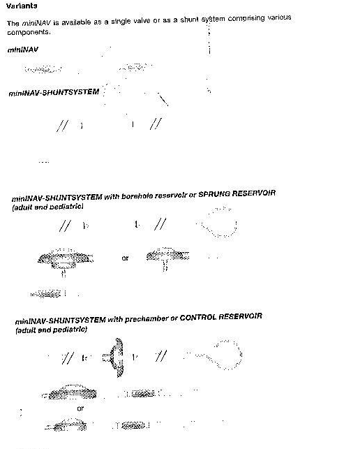
Possible shunt components
The miniNAV is available with different shunt accessories. These variants are comprised of a variety of components, which are described briefly introduced below:
The borehole reservoir is positioned in the cranial borehole. It allows measurement of intraventricular pressure injection of drugs and extraction of CSF. Its solid titanium base is highly puncture resistant. All reservoirs are available with integrated catheters or connectors. A special borehole reservoir is the SPRUNG RESERVOIR. An additional new feature of this reservoir is that CSF can be flushed towards the miniNAV because of a one way valve in the bottom of reservoir. By this mechanism flow in the direction of the ventricular catheter is avoided during the pumping procedure. The opening pressure of the shunt system is not increased by the implantation of the SPRUNG RESERVOIR.
The prechamber is positioned on the cranium. It allows measurement of intraventricular pressure, injection of drugs, extraction of CSF and palpatory ventricle inspection. Its solid titanium base is highly puncture-resistant. A puncture of the prechamber or the CONTROL RESERVOIR should be performed as perpendicularto the reservoir surface as possible with a cannula of maximum diameter 0.9mm.30 punctures are possible without any restrictions. A special prechamber is the CONTROL RESERVOIR. As an additional new feature of this reservoir, CSF can be flushed towards the miniNAV because of a one-way valve in the proximal inlet of the reservoir. By this mechanism flow in the direction of the ventricular catheter is avoided during the pumping procedure. The opening pressure of the shunt system is not increased by the implantation of the CONTROL RESERVOIR.
Tight tolerancing of the deflector ensures a good fit with the ventricular catheter. By adjusting the deflector (prior to implantation) the length of catheter penetrating into the skull can be optimised. The ventricular catheter is ‘’deflector’’ at a right angle in the borehole.
Tube systems
The miniNAV has been designed to ensure the optimal ventricular pressure. It is available as a shunt system or as individual valve units with or without an integrated distal catheter ( internal diameter 1.2mm, external diameter 2.5mm ) individual valve units should be used with catheters of approx. 1.2mm internal diameter and approx. 2.5 mm external diameter. The connector on the valve allows using catheters of 1.0mm to 1.5mm internal diameter. The external diameter of the catheter should be about double the internal diameter. Regardless the catheters must be carefully fixed with a ligature, to the valve connectors. It is essential that kinks in the catheter are avoided.
The included catheters have virtually no effect on the pressure-flow characteristics.
The miniNAV can be filled by aspiration through a sterile, single use syringe attached to the distal end of catheter.
The proximal end of the valve is immersed in a sterile, physiological saline solution. The valve is patent if fluid can be extracted in this way ( see fig.7 )
Valve test prior to implantation
Each miniNAV valve has been tested to ensure that the performance specifications given on the label are always met. The dynamic performance characteristics of the shunt can not be tested in a static test performed in the operating room.
If the surgeon wishes to verify, prior to implantation, that the shunt meets the specifications given by the manufacturer,the test described in the following can be carried out in the operating room:
Setting up the equipment
a) position the manometer and the water bath in such a way that the zero point of the manometer and the fluid level of the water bath are at the same height (see fig.8)
b) Fill the syringe, with the 5mm tip fitler attached with sterile water (always use the 5mm tip filter when topping up the syringe). Remove the tip filter when the syringe is full.
c) Connect the syringe, the manometer and the silicone tube with each other. Use the tube adapter if necessary (see fig8)
d) To release all air from the test assembly, turn the three-way faucet as shown in fig.9
e) Immerse the silicone tube in the sterile water bath and rinse it with the sterile water from the syringe.
1 miniNAV a horizontal, b vertical; 2 water bath; 3 constant water level; 4 silicone tube; 5 three-way tap; 6 single-use syringe with syringe filter; 7 manometer
Calibrating the equipment
a) Turn the three-way faucet as shown in fig.10 and fill the manometer to at least 5cmH2O
b) With the silicone tube immersed in the water bath, turn the three-way faucet so that the syringe is isolated from the manometer (see fig.11)
c) Allow the water comlomn in the manometer to drop.
d) The manometer has know been calibrated to the zero-level of the water bath. Fixate the manometer to maintain its position in relation to the water bath.
Test procedure
a) Connect the sterile shunt to be tested to the ready assembled, sterile test equipment.
b) Turn the three-way faucet as shown in fig.10 and fill the manometer to 10 cmH2O above the expected opening pressure. ( example: for testing a miniNAV with an opening pressure setting of 5cmH2O, the manometer is filled to 15cmH2O.)
c) Turn the three-way faucet as shown in fig.9 so that the manometer is isolated.
d) Remove all air from the shunt and the test setup by carefully rinsing it through with sterile water from the syringe.
e) Immerse the sterile shunt in the sterile water bath. The distal part of the shunt must be under water to obtain valid test results.
f) Carefully maintain a flow through the shunt and turn the three-way faucet as shown in fig.11 to isolate the syringe. As soon as the three-way faucet is in the correct position, the water colomn should begin to drop. The syringe is now isolated from the valve and it is not necessary anymore to maintain its flow. Repeat steps b to f if the water column fails to drop.
g) Allow the water level in the manometer to drop for 2 to 2.5 minutes. Read the resulting pressure at the manometer.
Test results- pre-implantation test
The pressure readings obtained by this method should yield the following results:
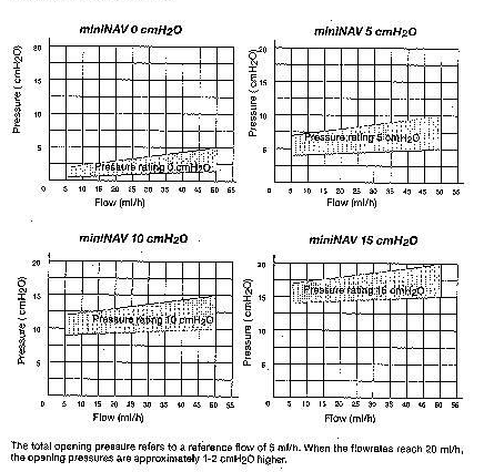
Pressure-flow characteristics
The diagrams below show the pressure-flow characteristics fort he pressure ratings in which the miniNAV is available.
Test on reflow safety
This test is carried out with the same equipment as the pre-implantation test. The shunt is carefully filled with sterile saline solution from the syringe before the air is removed from it (fig.11). the shunt is connected against the direction of flow (see arrow the shunt). The outlet of the shunt has to be at the zero level of the manometer. The manometer is filled up to 14 cmH2O (fig.12)
The three-way faucet is used for unblocking the flow to the shunt and blocking the flow to syringe. In this setup, no more than 2 drops (0.1 cc) per minute should emerge from the proximal part of the shunt (fig.13)
Caution: be careful to maintain sterility and to avoid particle contamination.
Surgical procedure
Positioning the ventricular catheter
Several surgical techniques are available for positioning the ventricular catheter. The necessary skin incision should be carried out, preferably, in the shape of a lobule pedicled towards the draining catheter or as a straight skin incision. To avoid CSF leakage, care should be taken that the dura opening is kept as small as possible after applying the borehole. The ventricular catheter is stiffened by the introducing stylet supplied with the product.
The miniNAV is available in different shunt variants:
When using a miniNAV-SHUNTSYSTEM with borehole reservoir or SPRUNG RESERVOIR, the ventricular catheter is implanted first. Once the introducing stylet has been removed, the patency of the ventricular catheter can be tested by checking if CSF is dripping out. The catheter is shortened and the borehole reservoir is connected, with the connection secured with a ligature. The skin incision should not be located directly above the reservoir.
The miniNAV-SHUNTSYSTEM with prechamber or CONTROL RESERVOIR comed with a deflector. This deflector is used for adjusting the position of deflection before implantation of the ventricular catheter. The catheter is deflected; the prechamber is put into place. The position of the ventricular catheter should be inspected again by postoperative CT or MR imaging.
Positioning the miniNAV
The miniNAV should be implanted in the head of the patient.
The valve is marked with an arrow pointing to distal(downwards) to indicate the flow direction. Whether the label faces towards the skin or the brain is of no importance in terms of the valve’s performance.
Following subcutaneous tunneling, the catheter is either pushed from the borehole, possibily through a reservoir, to the selected valve implantation site: or it is pushed through from the valve and connected to the reservoir, if there is any.
Positioning the peritoneal catheter
The access site for the peritoneal catheter is left to the surgeon’s discretion. It can be applied e.g. para-umbilically in a horizontal direction or transrectally at the height of epigastrium.
Likewise, various surgical techniques are available for positioning the peritoneal catheter.
We recommend pulling through the peritoneal catheter, using a subcutaneous tunneling tool and perhaps with an auxiliary incision, from the shunt to the intended position of the catheter. The peritoneal catheter, which is usually securely attached to the miniNAV has an open distal end, but no wall slits. Following the exposure of and the entry into, the peritoneum by means of a trocar, the peritoneal catheter (shortened, if necessary) is pushed forward into the open space in the abdominal cavity.
Re-implantation
Under no circumstances should products that have has previously been implanted in a patient be subsequently reimplanted in another, as a validated decontamination process will compromise the functionality of the valve.
Safety measures
The patients must be carefully monitored after the implantation. Reddened skin and tension in the area of the drainage tissue could indicate infections at the shunt system. Symptoms such as headache, dizzy, spells, mental confusion or vomiting are common occurances in cases of shunt dysfunction. Such symptoms, as well as shunt system leakage, necessitate the immediate replacement of the shunt component responsible, or of the entire shunt system.
Compatibility with diagnostic procedures
MRI examinations with field strengths of up 3.0 tesla and CT examinations can be carried without endangering or impairing the functionality of the shunt.
The miniNAV is MR conditional (ASTM-f2503-05). All components are visible via X-ray. The provided catheters are MRI safe. Reservoirs, deflectors and connectors are MR conditional.
Postoperative valve test
The miniNAV has been designed as a safe and reliable unit even without the implantation of a pumping device. However, the inclusion of a prechamber or a borehole reservoir allows the shunt system to be tested by flushing or pressure measurements.
Functional safety
The valves have been designed for long-term reliable and precise operation. Still, the possibility that the shunt system will need to be replaced for technical or medical reasons can not be excluded.
The valve and the valve system are able to resist positive and negative pressure up to 200cmH2O during and after implantation.
Sterilization
The products are sterilized with steam under closely monitored conditions. Double wrapping in sterile bags ensures sterility for a period of five years. The expiry date is printed on the wrapping of each individual product. Products taken from a damaged wrapping must not be used under any circumstances.
Resterilization
The descriptions and explanations given in this document are based on the clinical experience available to date. It is for the surgeon to decide if surgical procedures should be changed according to his or her experience and surgical practice.